
This tutorial will show you how to use a ARDUINO photogate for HIGH SPEED photography!
Please watch the following video before you go any further on this tutorial, It will show you a demonstration of how this works and run through the circuit and the code too.
Build the Photogate:
A Photogate or also known as a photo interrupter or optical interrupter is a device that is made up of a IR (infrared) led and a IR transistor with a gap between them. For more info on photo interrupter’s please check out my tutorial on them at this link: How to use photo interrupter’s with your ARDUINO. Small photogates can be scavenged from old printers and fax machines, but if you need a larger one then you will have to build it. I found that PVC pipe is a easy and cheap way to construct one but you can use wood or cardboard and that will work as well.
To build the photogate all you need to do is mount a infrared LED to one side of your gate and a infrared transistor to the other side, I found that a maximum of a two foot gate is about the maximum for a stable and reliable gate but it will work at 3 feet ++ just not as dependable. Also you could use a laser and photo resistor to accomplish the same task and have a very large gap between the two but I try to stay away from lasers because if you shine it in your eye you are blinded for life.. Below is a picture of my gate and you can see how it was made so im not going to explain all the dimensions, Just build it to what your needs are!

ARDUINO photogate for HIGH SPEED photography
Building the circuit..
PARTS LIST:
#affiliate links#
Six resistors (see schematic for values).
Two Plugs (one for your camera & one for your flash).
One infrared remote. (after some research I have found that sony and a few other remotes work differently so make sure you are using one that uses the same repeat code for every button).
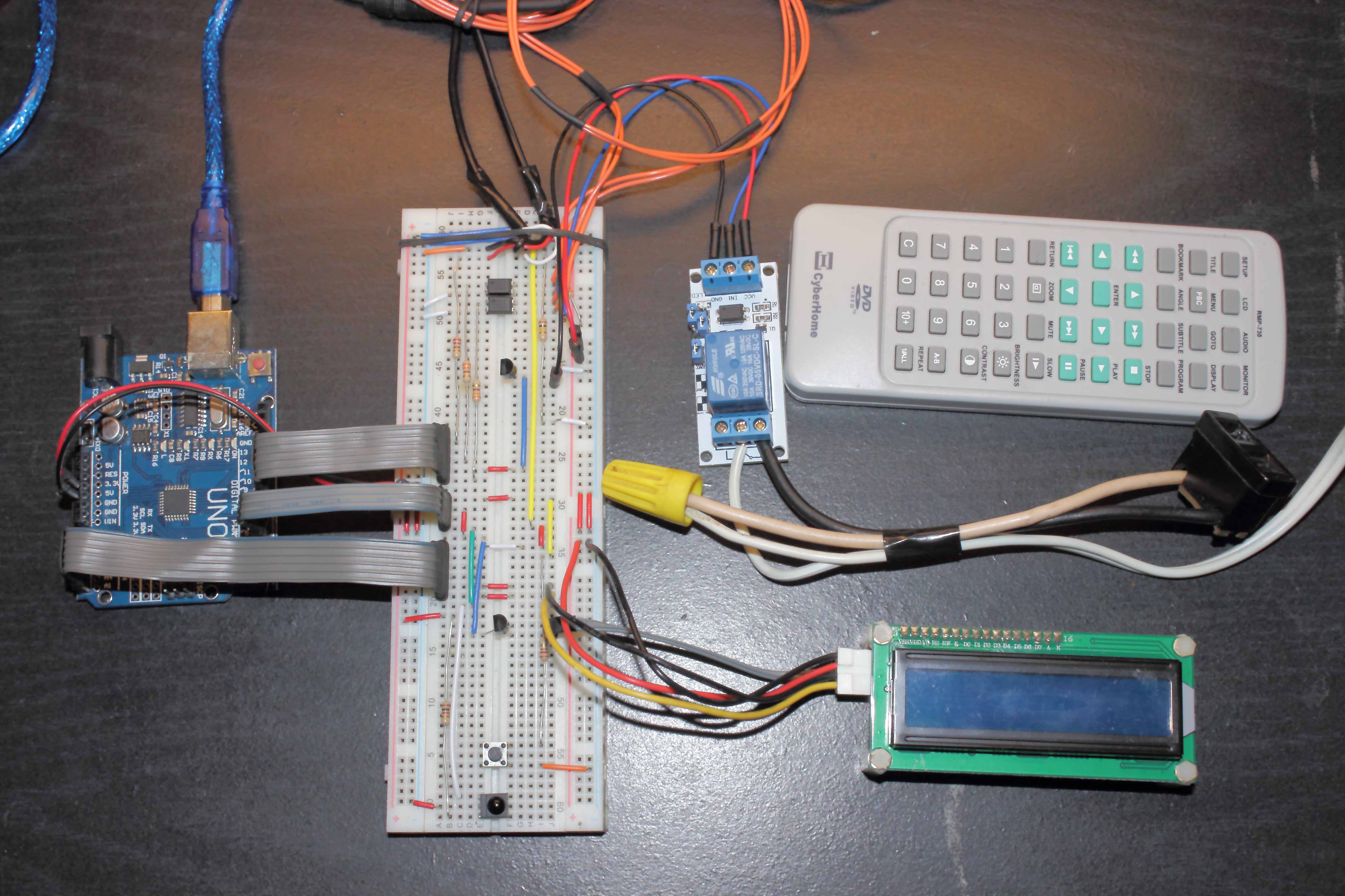
The following picture will show you the circuit you will need to build, You can down load it here so you can zoom in on it to see the connections easer.

ARDUINO photogate for HIGH SPEED photography
Before we go any further you will need to install two library’s that are not included with your ARDUINO IDE, these can be found at the following links:
After you have the library’s installed we can move on to the next step!
THE CODE.
you can copy and paste the code below into your ARDUINO ide or download the ide sketch here . The video link at the beginning of this tutorial will show you how to map you remote and give you a walk through of this whole project, so if you skipped it please go back to the beging and watch it…
// ARDUINO photogate for HIGH SPEED photography //
#include <Wire.h>
#include <LiquidCrystal_I2C.h>
LiquidCrystal_I2C lcd(0x3f, 2, 1, 0, 4, 5, 6, 7, 3, POSITIVE);
#include <IRremote.h>
#define RECV_PIN 4
IRrecv irrecv(RECV_PIN);
decode_results remote;
#define irLed 12 //ir led on pin 12
int button = 0; //ir button tracker
int fdel = 0; //flash trigger delay
int pdel = 0; //last flash trigger delay
int camb = 10000; //camera bulb time
int pcamb = 10000; //last camera bulb time
#define camt 10 //camera trigger pin
#define flash 8 //flash trigger pin
int b = 0;
int x = 0; //while loop hold
int y = 0; //while loop counter
int z = 0; //push button while loop
int irt; //ir transistor value
int pirt; //last ir transistor value
int irTrigger = 900; // flash trigger threshold
int pirTrigger = 900; //last flash trigger threshold
#define pButton 7 //push button on pin 7
#define lcdLight 6 //lcd back light on off pin 6
#define relay 9
void setup() {
// Serial.begin(9600); // for testing
lcd.begin(16, 2); // initialize the lcd for 16 chars 2 lines
lcd.clear();
irrecv.enableIRIn(); // Start the receiver
pinMode(irLed, OUTPUT);
pinMode(camt, OUTPUT);
pinMode(flash, OUTPUT);
pinMode(pButton, INPUT_PULLUP);
digitalWrite(irLed, HIGH);
pinMode(lcdLight,OUTPUT);
digitalWrite(lcdLight,HIGH);
pinMode(relay,OUTPUT);
}
void loop()
{
// irt=analogRead(A0); //ir transistor value 4 testing
// Serial.println(irt);
digitalWrite(lcdLight,HIGH);
//// keep lcd display correct////
fdel = constrain(fdel, 0, 999);
if (fdel == 9 && pdel == 10 || fdel == 99 && pdel == 100)
{
lcd.clear();
}
pdel = fdel;
camb = constrain(camb, 3000, 30000); //3-30 sec bulb time
if (camb == 9500 && pcamb == 10000)
{
lcd.clear();
}
pcamb = camb;
irTrigger = constrain(irTrigger, 100, 1022);
if (irTrigger == 999 && pirTrigger == 1000)
{
lcd.clear();
}
pirTrigger = irTrigger;
//////////LCD data//////////
lcd.setCursor(0, 0);
lcd.print(“DEL:”);
lcd.setCursor(4, 0);
lcd.print(fdel);
lcd.setCursor(8, 0);
lcd.print(“IRT:”);
lcd.setCursor(12, 0);
lcd.print(irTrigger);
lcd.setCursor(0, 1);
lcd.print(“BULB TIMER:”);
lcd.setCursor(11, 1);
lcd.print(camb);
//////////check for ir input//////////
if (irrecv.decode(&remote)) {
//////////this is for mapping your remote//////////
//Serial.println(remote.value);
//////camera triger stage//////
if (remote.value == 1320368837)
{
lcd.clear();
digitalWrite(lcdLight,LOW); //turn lcd off
digitalWrite(relay,HIGH); //turn light off
delay(1000);
digitalWrite(camt, HIGH); //open camera shutter
x = 1;
while (x == 1) // hold for ir threshold to be triggered
{
y = y + 1;
delay(1);
irt = analogRead(A0); //read ir transistor
// Serial.println(irt); //for testing
if (irt < irTrigger) // triger the flash
{
delay(fdel);
digitalWrite(flash, HIGH);
delay(20);
digitalWrite(flash, LOW);
x = 0;
y = 0;
delay(100);
digitalWrite(camt, LOW);
delay(1000);
digitalWrite(relay,LOW);
}
else if (y > camb) //exit if nothing happens
{
digitalWrite(camt, LOW);
digitalWrite(relay,LOW);
x = 0;
y = 0;
}
}
}
//////////IR codes for changing variables//////////
/////flash delay/////
else if (remote.value == 1320358637)
{
fdel = fdel + 1;
button = 1;
}
else if (remote.value == 4294967295 && button == 1)
{
fdel = fdel + 1;
}
else if (remote.value == 1320368327
)
{
fdel = fdel – 1;
button = 2;
}
else if (remote.value == 4294967295 && button == 2)
{
fdel = fdel – 1;
}
/////camera bulb time/////
else if (remote.value == 1320392807)
{
camb = camb + 500;
button = 3;
}
else if (remote.value == 4294967295 && button == 3)
{
camb = camb + 500;
}
else if (remote.value == 1320360167)
{
camb = camb – 500;
button = 4;
}
else if (remote.value == 4294967295 && button == 4)
{
camb = camb – 500;
}
/////IR TRIGGER/////
else if (remote.value == 1320401477)
{
irTrigger = irTrigger + 1;
button = 5;
}
else if (remote.value == 4294967295 && button == 5)
{
irTrigger = irTrigger + 1;
}
else if (remote.value == 1320417287)
{
irTrigger = irTrigger – 1;
button = 6;
}
else if (remote.value == 4294967295 && button == 6)
{
irTrigger = irTrigger – 1;
}
/////keep other buttons from triggering repeat/////
else
{
button = 0; //reset remote button
}
irrecv.resume(); // Receive the next value
}
/////push button/////
if (digitalRead(pButton) == LOW)
{
lcd.clear();
z = 1;
delay(500);
while (z == 1)
{
irt = analogRead(A0); //read ir transistor
//keep LCD stable//
if (irt< 9 && pirt > 10 || irt < 99 && pirt > 100 || irt < 999 && pirt > 1000)
{
lcd.clear();
}
pirt = irt;
lcd.setCursor(2, 0);
lcd.print(“IRT MONITOR:”);
lcd.setCursor(6,1);
lcd.print(“#”);
lcd.setCursor(7, 1);
lcd.print(irt);
delay(500);
if (digitalRead(pButton) == LOW)
{
z = 0;
lcd.clear();
delay(500);
break;
}
}
}
/////how fast values change delay/////
delay(125);
}


